![]()
Version 3.8 is designed for graphic-aided design of new central heating systems and regulation of already existing ones. This program allows to design pipe systems in the chilled water installations. catalog database program contains information about pipes, valves and heaters manufactured by leading companies, both domestic and foreign. The high flexibility of the program makes that in one projec can also be used fittings, pipes and radiators of different companies.
Program Audytor C.H. makes it possible to design very large systems (up to 12 000 heaters).
The program allows to perform full system hydraulic calculations, therefore it:
- selects pipe diameters.
- specifies the hydraulic resistance of individual cycles, taking into account the graviational pressure resulting from the cooling water in the pipes and the heat exchangers.
- gives the total pressure loss in the system
- reduces the excess pressure in the circuit by initial tuning of the dual control valves or through the selection of throtling orifice diameters
- takes into account the necessity to ensure the suitable hydraulic resistance of heat receiver (Dpgmin.)
- adjusts presets of the differential pressure setting installed in the places elected by he designer (the base of the vertical branch of the system, etc.)
- takes into consideration the requirements regarding the authorities of thermostatic valves (suitable for valves, pressure drops)
- selects exchanger residential nodes and thermal buufers cooperating with residential nodes.
- selects pumps and groups of pumps.
- allows the use of hydraulic clutches.
- allows the use of dual manifolds.
The thermal calculations program performs the following functions:
- specifies the heat gains form pipes in individual rooms
- estimates heating agent's flow in already existing heat receivers taking into account it's cooling in pipes and heat gains from pipes
- takes into account water cooling in pipes and it's influence on gravitational pressure
- estimates heat gains and water cooling in pipes
- determines the required size of radiator for a specific heat demand
- designs floor heaters
Software operation
Working in MS Windows environment makes the program user-friendly. Principles of cooperation with other standard programs for MS Windows make easier the use for those familiar with Windows enviroment.
The program uses a lot of solutions that simplify and streamline work. The most important of these are:
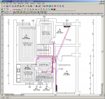
- Graphical data entry process gives the opportunity to present the results of calculations in the installation diagram
- Help system – while performing calculations the program will store error warning message and info on detected error
- The ability to view multiple types of data, results, etc. simultaneously
- Access to the help info on quantities being entered
- Fast access to data directory: pipes, radiators and valves.
Entering data
Thanks to graphic designing process, most info on the installation being designed is entered into the drawing of the installation diagram. Necessary information on the drawn elements are introduced in the tables associated with the installation diagram. This makes it possible to edit both single wires, radiators, fittings and whole selected group.
The program checks, whether no errors, disabling the continuation of calculations, have been encountered. If further calculations are not possible, the calculations’ process is stopped. Info on errors is stored in the file with encountered errors.
In order to facilitate the entering data process the program is equipped with:
- simultaneous edition of more than one system element
- the ability to use ready blocks
- function of copying any fragment of the picure vertically or horizontally, togheter with automatic renumbering of rooms and pipe-runs
- function of defining unlimited number of own blocks consiting of freely selected fragments of the picture
- fast access to help info on quantities being entered
- fast access to the most commonly viewed stsre elements, with the application of pull-down buttons,
- dynamic linking of data in the picture with the reevant table data
- aided linking of pipes, fittings, radiators and other system elements
The program gives the possibility of individual parameter settings for many simultaneously selected drawing elements. The edited items are highlighted in the table on the installation diagram thanks to link between the drawing and the table data.
The program is accompanied with the library of the typical picture fragments (blocks), such as storey risers, dwelling system- and manifold elements, and enables fast creation of the installation diagram. Additionally, the user has the possibility to define practically unlimited number of own blocks consisting of freely selected picture fragments. Such blocks can be then used in following projects
Thanks to the copying function for the freely selected picture elements, it is possible for example to enter the fragment of the installation diagram onto the whole storey (subsequent risers or dwelling systems), and then automatically create the diagram and data for the subsequent storeys.
Design of underfloor radiators
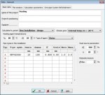
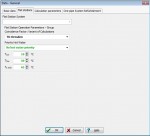
The program has a built-in underfloor radiator module. The module is an integral part of the graphical system of design of the central heating.
The first step is to draw a ceiling structure, in which the pipe coil. It is possible to create a whole directory of the most common structures, which can then be used in the following projects. It is advised to start the design of the underfloor radiators with defining their specification. Thanks to the function of reading of the underfloor radiators' types from other files, the data entered in other project can be used in the current project.
Floor projections
The program allows to draw storeys on the views. Thanks to that, when using the program you can create the whole drawing specification for the central heating installation’s design. It is necessary to draw a floor plan, and then enter the radiators, pipes and other components. The program describes the radiators and then gives pipe diameters and valve settings.
If drawings are available in the electronic form (CAD, CorelDraw, MS Word drawings), it is possible to copy them directly to the program and use as architecture drawings. The program accepts the drawings in WMF and BMP formats. This allows the close cooperation between the architect and the designer of heating system. It contributes to a significant shortening of the design process.
Data control and calculation results
While entering data the program maintains the control of their correctness.. The program will store error warning message and info on detected errors in the error file. Error list window has been equipped with the function of positioning errors. The program will highlight the relevant fragment of the picture and display the data table, marking the cell referring to the error that has been found.
The error diagnostics allows the designer to evaluate the quality of the project. The program features a fast search mechanism that indicates he place of error(finds the tables, rows and columns with incorrect data and identifies incorrect components in the installation diameter).
Calculations results
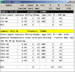
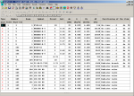
Calculations results can be viewed both in table- and in graphic format, as well as table form. Picture layers format and label format for individual system components can be freely modified (the choice of highlighted quantities, color, font size, etc.). Calculations results can be also presented in the system plan view.
The contents of all tables can be formatted (choice of shown columns and rows, font size) and sorted according to freely selected filter. Tables with calculations results can be printed and moved to other applications functioning in the Windows environment (eg. spreadsheet, word processor, etc.). Print preview function enables viewing the pages before printing.
Calculations results as plan views and installation diagrams can also be plotted onto the plotter or printer. The user can choose the plotting scale. Plot preview function enables to check the pictures before plotting. Larger pictures are printed or plotted in fragments which then can be combined into one-piece printout, so even large pictures can be executed with the ordinary A4 printer.
The program is equipped with a function to save drawings in DXF or DWG format. Saved drawings can then be loaded into the program such as Auto CAD. Drawing in DXF or DWG format is divided into layers, and the typical components of the system are stored in the form of blocks.The tables with the results of calculations can be printed as well as transferred to other applications running in a Windows environment (such as a spreadsheet, word processor, etc.).
Print Preview function allows you to view the appearance of the pages before they are printed on paper. Program Auditor C.O. 3.8 has been designed to work with the program OZC Auditor 4.0 and newer versions (5.0 OZC 3D). Program C.O. version 3.5 or lower is not possible to import data from the latest public version of OZC. Auditor C.O. 3.8 runs on both 32 and 64 bit Windows XP, Windows Vista and Windows 7.


