


POSSIBILITY OF DESIGNING SURFACE SYSTEMS!
The latest version of the KAN SET 7.4 program introduced the possibility of designing surface systems - a ceiling system and a wall system. The program was enhanced with a feature that calculates the resulting cooling efficiency of the installation.
 |
 |
||
| DOWNLOAD THE FREE UPDATE | ORDER THE PROGRAM |
New features
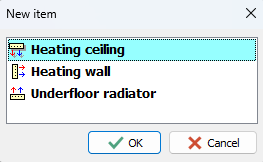
- Surface systems - a ceiling system and a wall system
- Calculations of resulting cooling efficiency of the installation
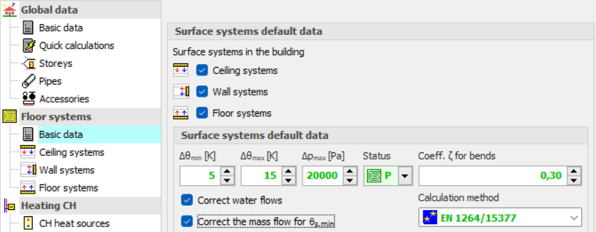
Surface systems
The new version of the program allows to design ceiling and wall systems. Among the surface systems, we also will find the well-known floor system.
Before starting the design of the surface system, the user should declare the parameters related to the radiator's constrution. The constrution data will be automatically inherited directly into the drawning, significantly reducing the data entry time.
The tab - Data - Surface Radiator Construtions allows you to add new radiator constructions.
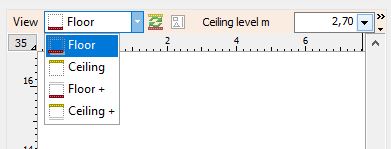
The new version of the program enables the modification of the drawing view based on the designed systems.
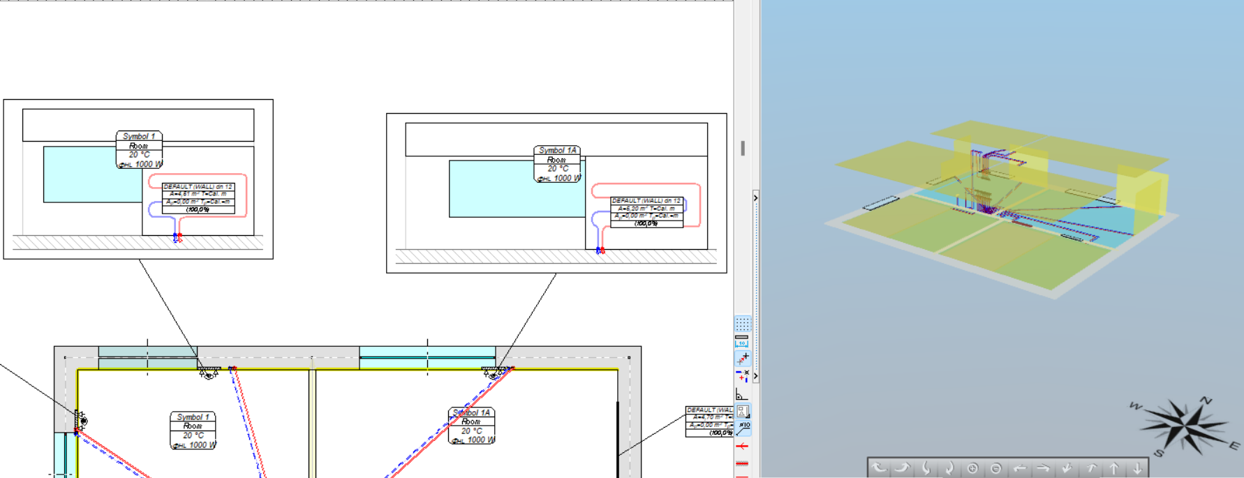
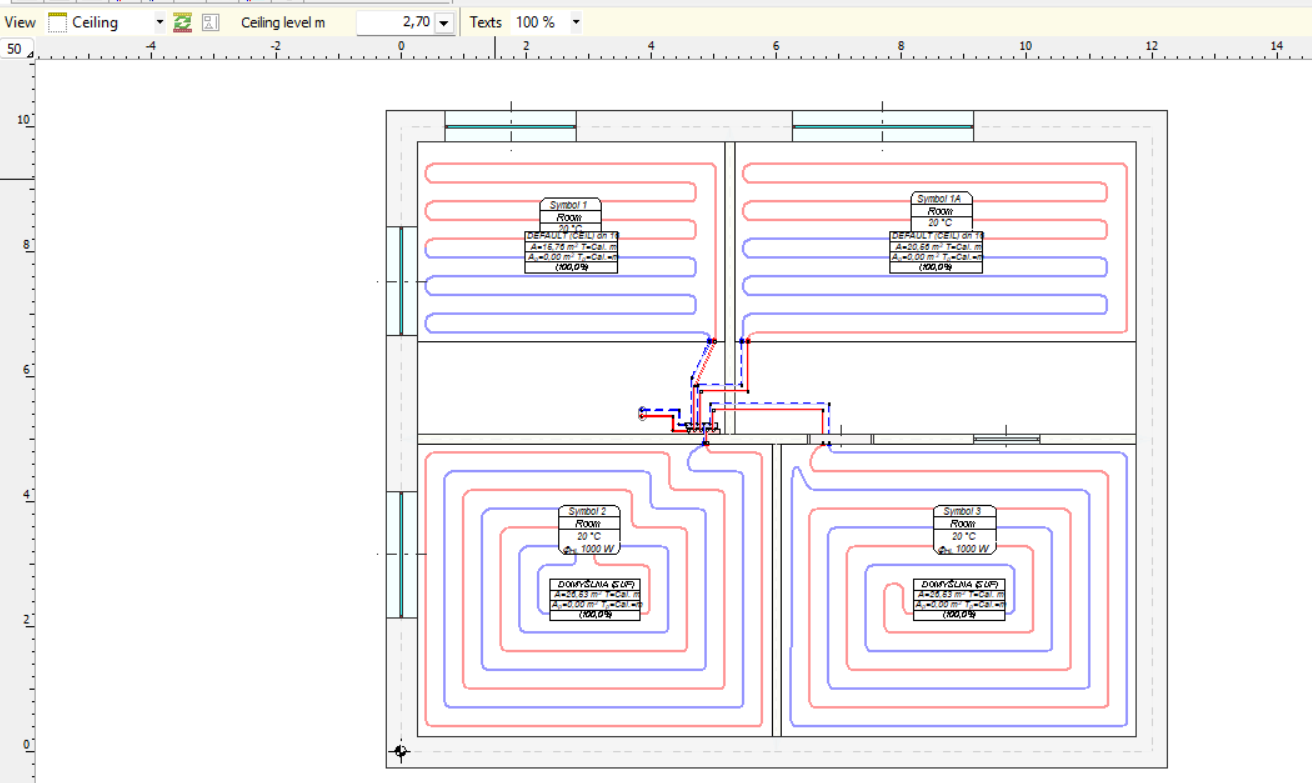
Both the ceiling and the wall systems can be designed in plan view as well in diagram.
The wall system
When designing a wall system, there are two options for adding receivers: you can insert a simplified graphical symbol of the radiator into the drawing, or you can insert a so-called drawing symbol into the wall, then edit the wall and draw the shape of the radiator. The second option is only applicable to plan view design.
The ceiling system
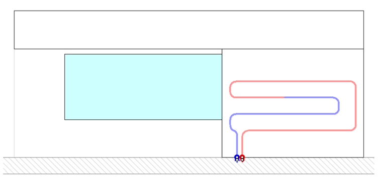
When designing a ceiling system, it is necessary to switch the view from the floor plan to the ceiling view. In this layer, we can outline the area for ceiling heating. It is essential to introduce risers from both the ceiling and floor levels. This way, we connect the installations to the source. This is necessary to perform complete calculations in the program.
If we design the central heating system in plan view, the program will automatically generate a 3D visualization, allowing us to precisely check whether all elements are connected, whether the receivers are at the correct level, and whether there are any collisions between the pipes.
Both the ceiling and the wall systems can be designed in the plan view as well in diagram.
Calculations of the resulting cooling efficiency of the installation
The new version was improved with a funcion that calculates the resulting cooling efficiency of the installation.
After designing the surface installation with heating parameters, the program will determine the resulting cooling power when switched to cooling mode.
These calculations will be performed if the CC module is activated in the general data

and if in CH Heat Sorce Tab the Calculate Cooling option is enabled
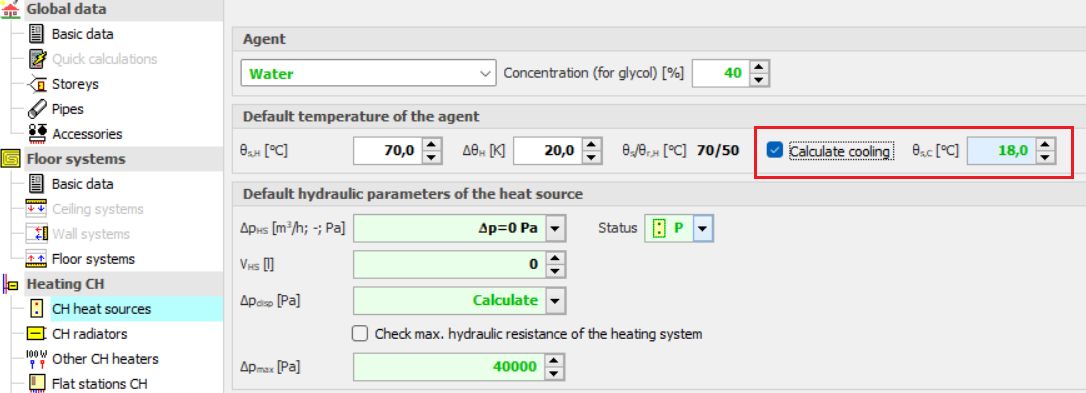
The program uses the same flow rate of the agent in cooling mode as in the heating system. After performing the calculations, the results can be read both on the drawing – for example, on a tabular label attached to the manifold – and from the general tabular results.