


New possibilities!
New concept of work with SET program
 |
 |
 |
||
| DOWNLOAD THE FREE UPDATE | ORDER THE PROGRAM | WATCH THE FILM |
The main changes are:
The latest version of Auditor SET introduced new features and a number of improvements to speed up the installation design process:
- New concept of work with SET program.
- New Fast Calculation (FC) module, which allows you to perform fast, approximate calculations of the thermal load of rooms and preliminary calculations of installations.
- Improvements in the design process of surface installations.
- Changed layout of the bill of materials.
- Changed module for viewing catalog data and selecting devices from catalogs.
- Improvements related to drawing wires.
- Improvements in graphics.
New concept of work with SET program
The new Fast Calculation (FC) module in the SET Audytor provides the opportunity for simplified installation design. It also makes it possible to speed up the creation of professional designs.
In professional design mode, elements of simplified design can be used to streamline the design process (fast estimation of heat loss in the absence of results from the OZC program, selection of space heating concepts, etc.).
Both the simplified design and the detailed professional design are saved in the same file, which facilitates further work with the project.
Two models of work with SET program
The first model – fast calculations
This model involves the initial sketching of the installation on the plan. At this stage, the drawn installation layout can be calculated on a current basis.
The program tries to calculate the sketched diagram, without paying attention to the full completeness and full correctness of the data.
At this stage it is already possible to draw manifolds, radiators and routes for connecting radiators to manifolds. This allows you to quickly develop and pre-calculate the installation concept.
The second model – professional, full calculations
Based on the data from the first model, after completing all the data, it is possible to perform full professional calculations of the entire installation, including detailed data diagnostics.
Advantages of such solution:
- Ability to stage the work and evaluate the solutions adopted at each stage and create a bill of materials.
- Ability to work as a team from construction concept to detailed design.
- Ability to change the concept at the project coordination stage fast.
- For more complex projects, the work can consist of three stages.
Stage 1. Concept development
A more experienced designer can develop the first stage, in which he/she will suggest the use of appropriate solutions and to some extent diagnose where problems may occur. He/she can also make a preliminary cost assessment.
Stage 2. Design detailing
The second stage is created by designers, engaged in drawing systems, without necessarily having extensive design experience. The second stage can be used to prepare the construction design and, to some extent, inter-industry coordination.
Stage 3. Development of the final technical design
The third stage is to combine the previous sketches into a single professional design with the risers, all control elements and a complete installation diagram.
This stage is performed by an experienced designer who is able to evaluate the final results and make the necessary corrections.
The Fast Calculation module can effectively support design work at every stage.
In addition, a 3D model, axonometry drawing and bill of materials can be used all the time.
Drawings from each stage can be printed, exported to DWG file, as well as transferred to Revit.
Fast calculations of room thermal load
Version 7.3 has additional function to estimate the value of room thermal load in a simplified manner based on few basic parameters.
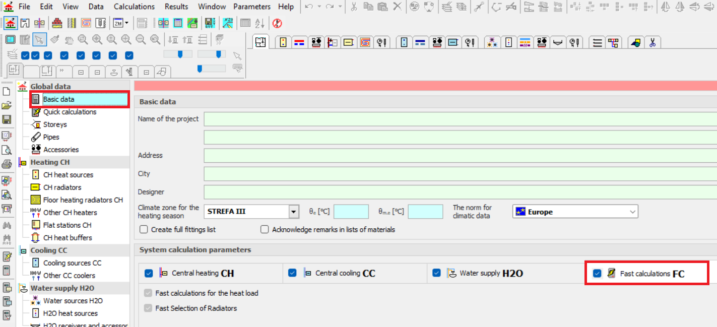
In order to use this function, select Quick Calculation option in Global Data on the Basic Data tab.
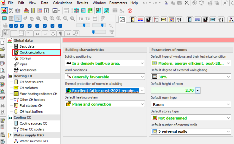
Then, define Building Characteristics and the default Room Parameters in the Quick Calculation tab.
By drawing rooms on the floor plans, we can estimate the heat output required to heat the room fast.
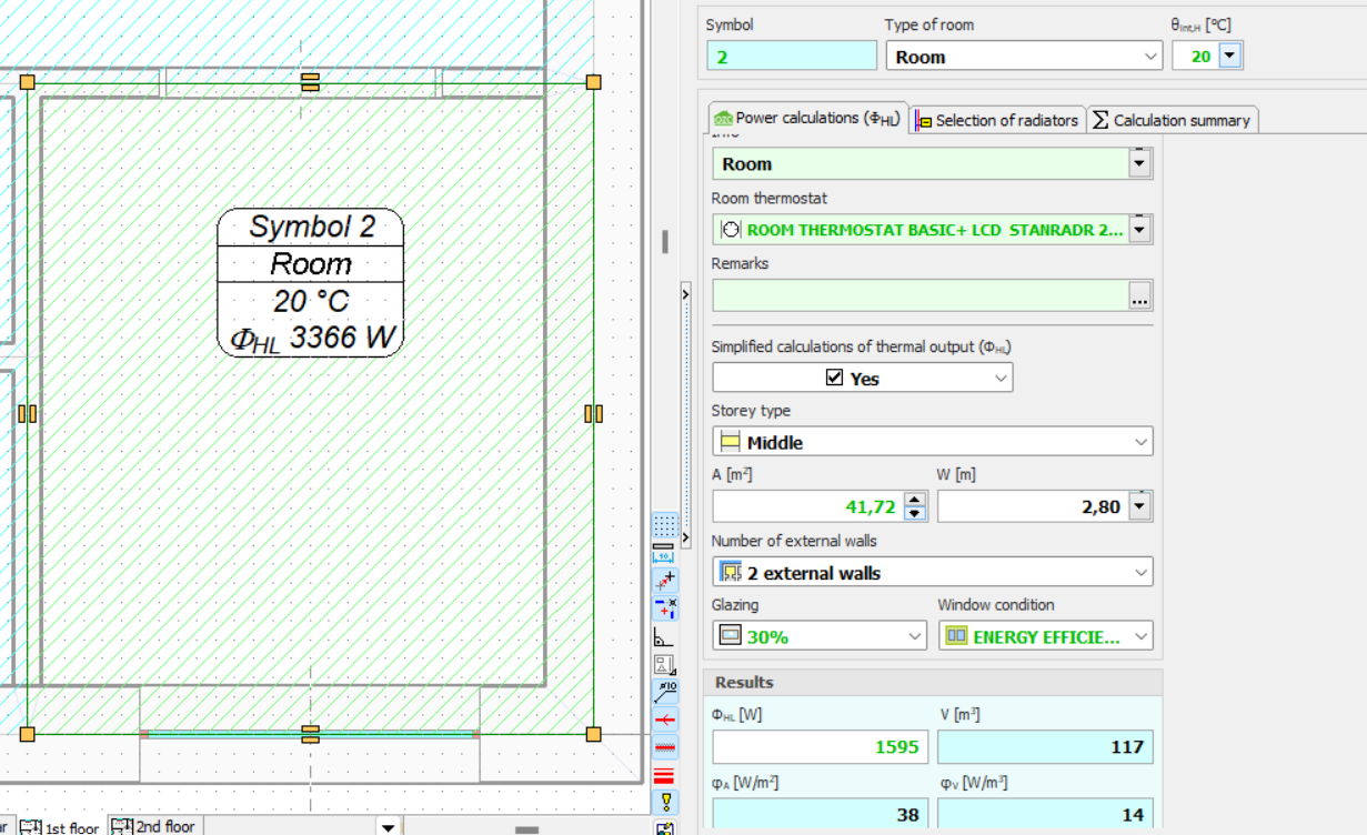
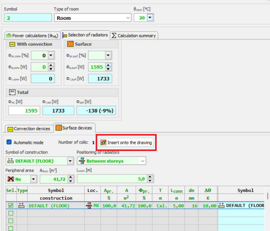
The program also performs an estimated Radiator Selection.
Thanks to this function, the designer can select the appropriate method of heating the room and get an idea of the type of heating equipment to be used in the room.
The surface layout suggested by the program can be inserted into the floor plan drawing.
Fast installation calculations
The Fast Calculation function allows you to draw fragments of an installation and perform ongoing calculations. The program tries to calculate the sketched diagram, without paying attention to the full completeness and correctness of the data. For example, you can draw convection heaters and floor radiators only without connection pipes.
Then you can perform Fast Calculation.

Despite the fact that the radiators are not connected to the wiring network, the program will choose their size in an approximate manner (without taking into account the actual supply temperature values).
This allows you to estimate the thermal efficiency of the adopted solution without having to draw the entire installation diagram.
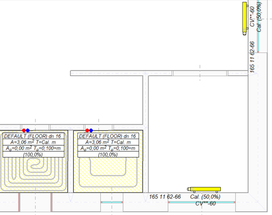
The Fast Calculation function tries to select installation components even if they are not correctly connected to the network of wires and sources. If the Global Data of the project is correct, the program tries to create virtual sources, supplying the drawn parts of the installation.
Fast Calculations are performed for all installations (CH, CC and H2O).
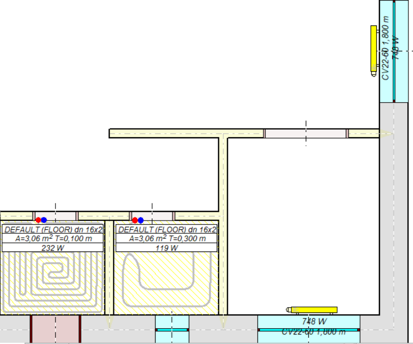
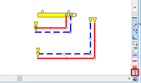
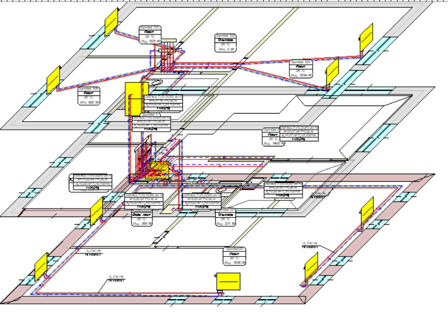
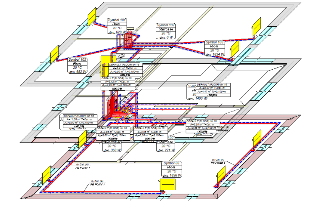
In the figure below, some of the CH pipes are not connected to the receivers and the radiator in the lower part of the picture has incorrect data.

By performing fast calculation, the program created virtual sources where it made sense and matched the pipes and receivers.
Pipes not connected to the receivers and the radiator with incorrect data were not matched.

Improvements in the design process of surface installations
The Fast Calculation function is especially useful in the design process of surface installations.
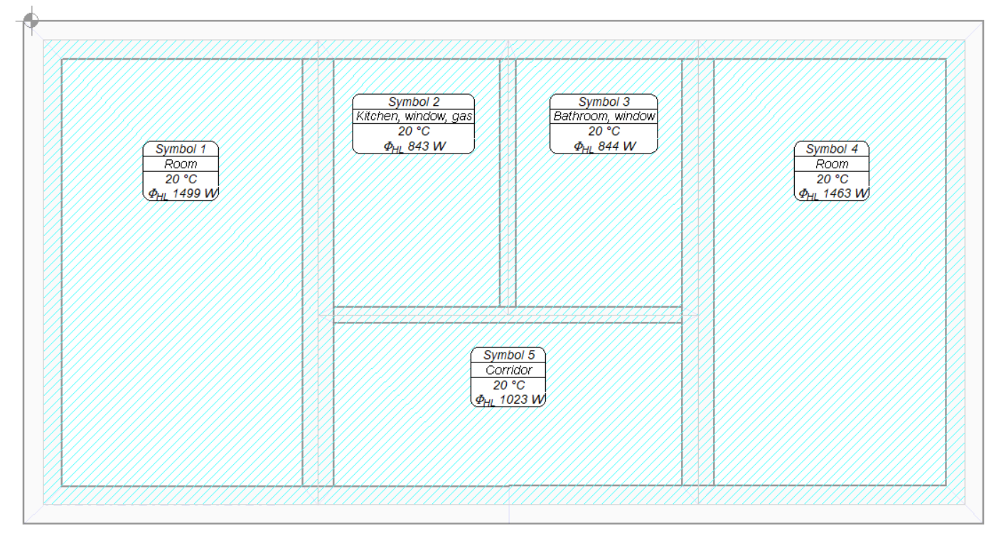
The design starts with the preparation of a building base with room zones. The function of Fast Calculation for Room Heat Load, discussed earlier, can be used to calculate the heat demand.
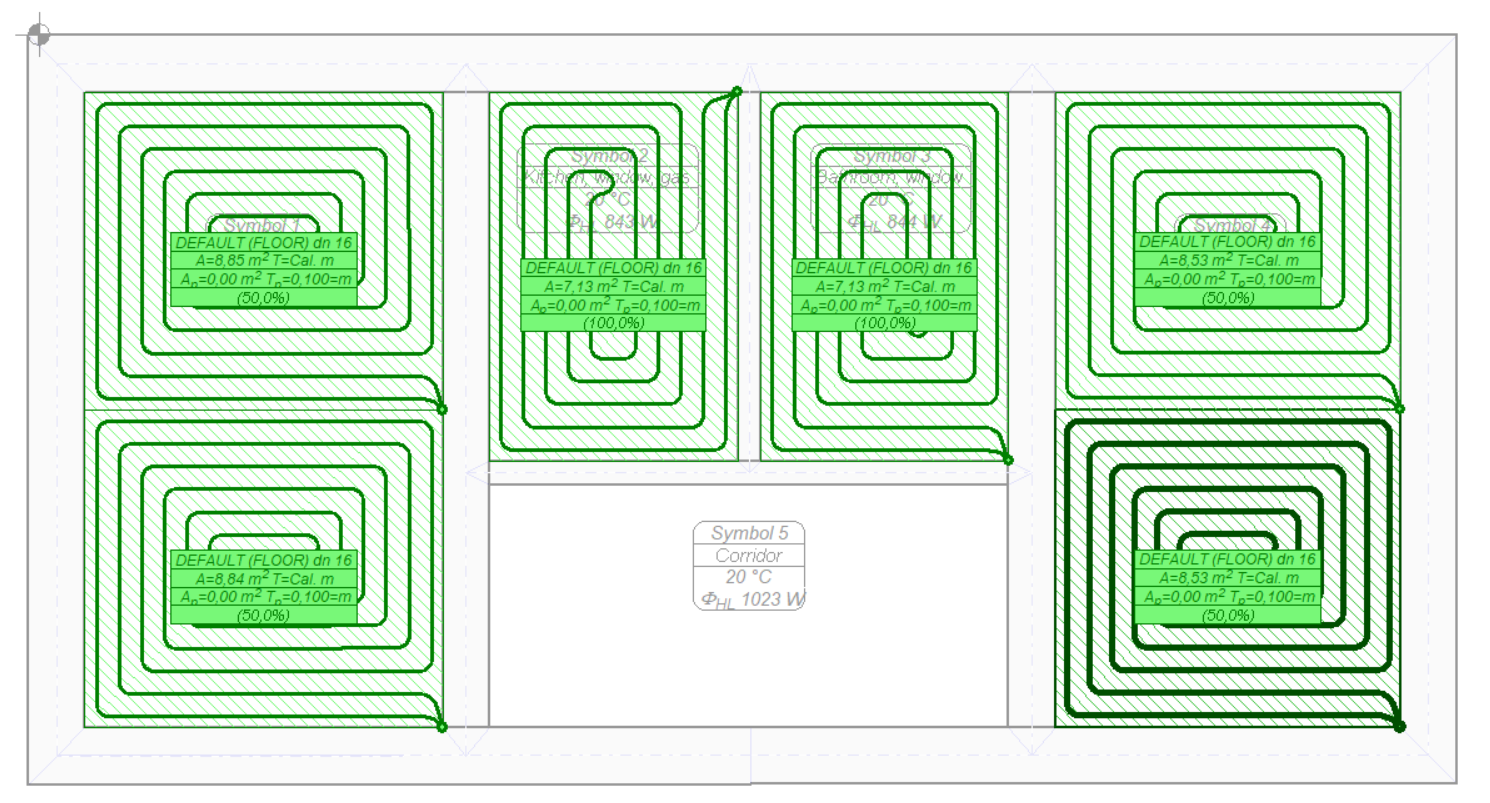
Then, the radiators are inserted in the rooms with the use of buttons in the Floor Radiators tab.
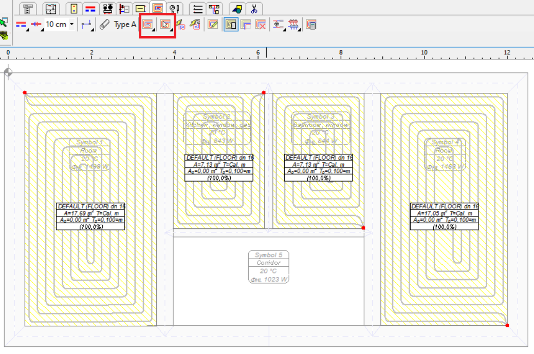
For such a drawing, Fast Calculation can be already performed to determine the operating conditions of individual radiators. However, a better solution at the beginning of the design process is to make Fast Calculation for Floor Radiators.
Before calling this command, select the radiators for which you want to make calculations.
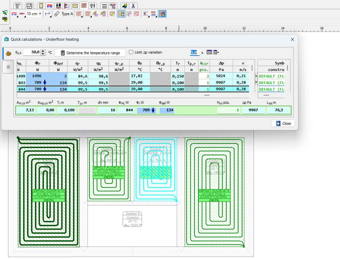
As part of this calculation, the optimal supply temperature can be determined and the issue of whether some radiators should be divided into several circuits can be checked. The table of Fast Calculation for Floor Radiators allows you to track multiple parameters. If manifolds with mixing systems are used, the specified supply temperature should be entered into the manifold data or the heat source data in the Global Data.
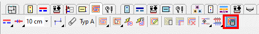
If the program informs you in the Ncir column that the number of circuits should be higher, the button on the right side of the cell can be clicked to divide the radiator into several circuits.

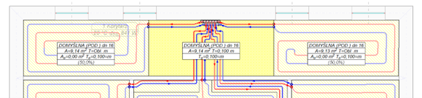
In the next step, insert a manifold (a pair of manifolds, to be precise) intended for radiators and select the manifold along with the radiators to be connected to it.
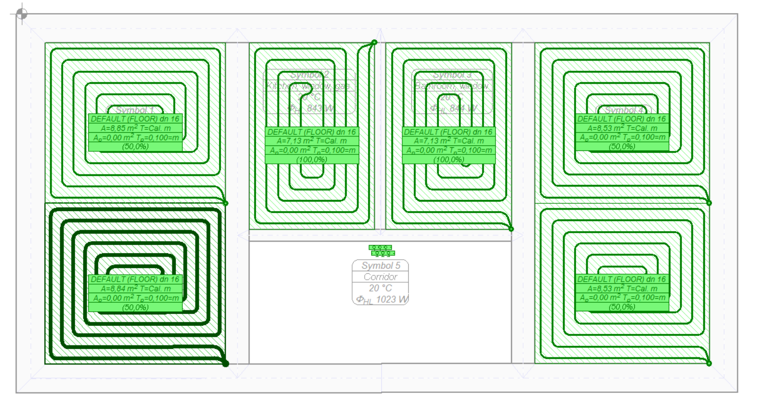
Using the command to Automatically connect selected floor radiators to manifolds, simplified wire routes are created.

After creating pipe routes connecting radiators with manifolds, it is possible to perform fast calculation again. The program will convert the pipe route into virtual supply and return pipes during the calculation. More precise calculation will take into account the cooling of the medium in the pipes.

Since the virtual pairs of wires look unrealistic, we may not want to show them in the drawing. To do this, turn off the Show Virtual Connections option in the lower right corner of the Drawing window with calculation results.

If the results of the initial calculations are correct and we do not need to change the number of floor radiators or their location, we can proceed to give the connection routes real shapes.
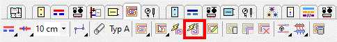
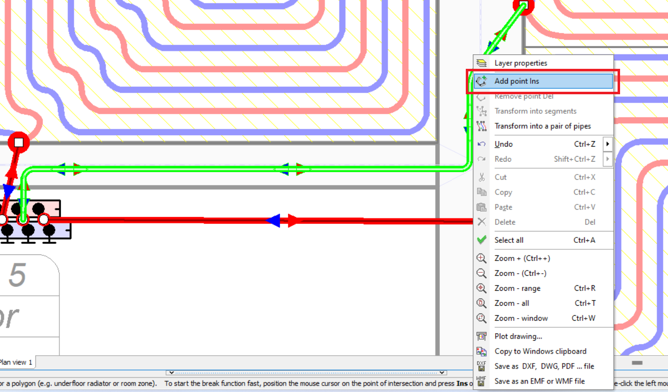
The connector route is a curve to which we can add more points. To do this, hover the mouse cursor over the curve, press the right mouse button and then select Add Point from the displayed menu. We can alternatively use the Ins key.
We proceed by analogy to delete the point of the curve, remembering to select the curve beforehand.

We can also draw pipe routes connecting radiators to manifolds manually by selecting the Rote of pipes – heating command.
Note!!!
Pipe routes are connected to the radiators (floor and convection) and manifolds only. They are not connected to other pipes and other devices.

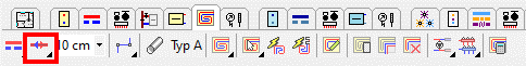
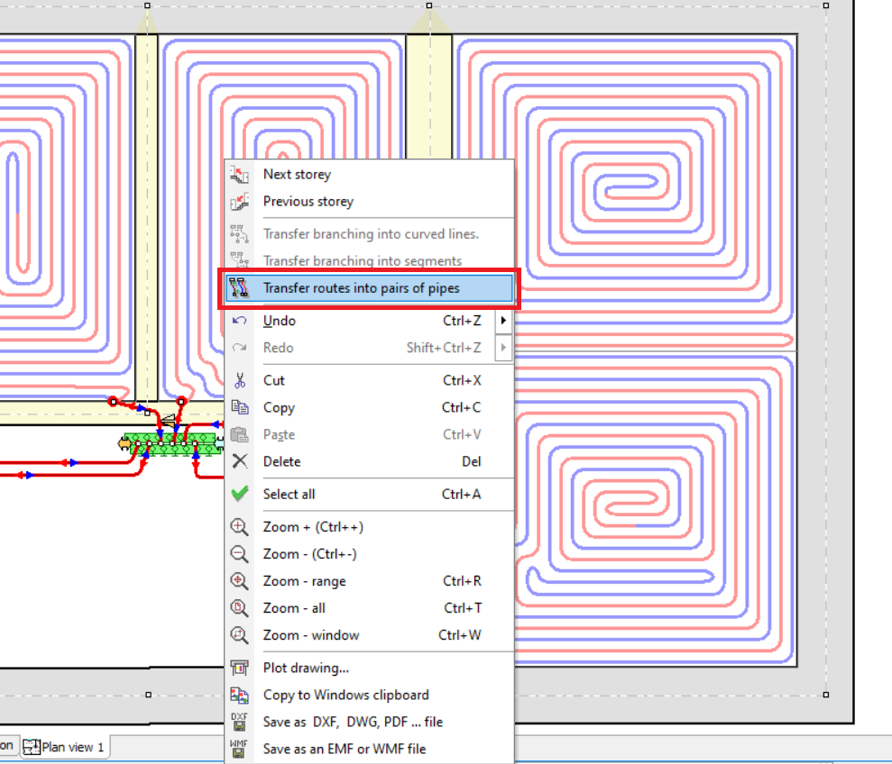
Pipe routes can be transformed into pipe pairs. To do this, with the mouse cursor placed over the manifold, press the right mouse button and select the Transfer routes into pairs of pipes command.
It may happen that some connections run through radiator zones.

In this case, to correct this, select these radiators and choose the Automatically trim the heating zones of the selected underfloor radiators command.

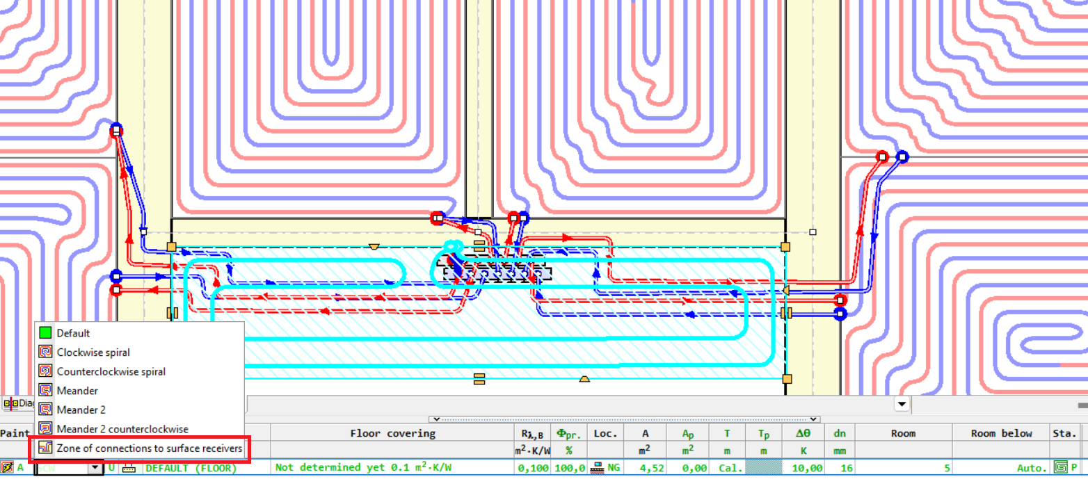
A zone of connections to surface receivers can be additionally added.
To do this, insert a floor radiator at the location of the zone and select the option Zone of connections to surface receivers in the table of its properties in the column System.

Note!!!
The adopted average spacing has a significant impact on the specific heat output obtained from the connections. The length of the connections is given in the drawing and does not depend on the adopted average spacing. The specific thermal power obtained from one meter of connection increases with the pipe spacing. In practice, this means that for the same length of connections, zones with greater spacing have more thermal power. For this reason, the program assumes a small spacing (0.1 m) by default, so as not to overestimate the power obtained from the connections.
In the Fast Calculation window for floor radiators, a tab with calculation results for the cooling function has been added. Radiator selection is performed for heating mode. In the case of the cooling function, the program calculates the parameters of a previously selected radiator when it is supplied with a cooling medium. For example, the cooling capacity of the device designed for heating conditions can be determined.

New items have been added to the manifold table label. In the latest version of the program, it has the following form:

New layout of the bill of materials
The layout of the bill of materials has been changed in the program, making it more readable.
A tab to Print bills of materials has also been added.
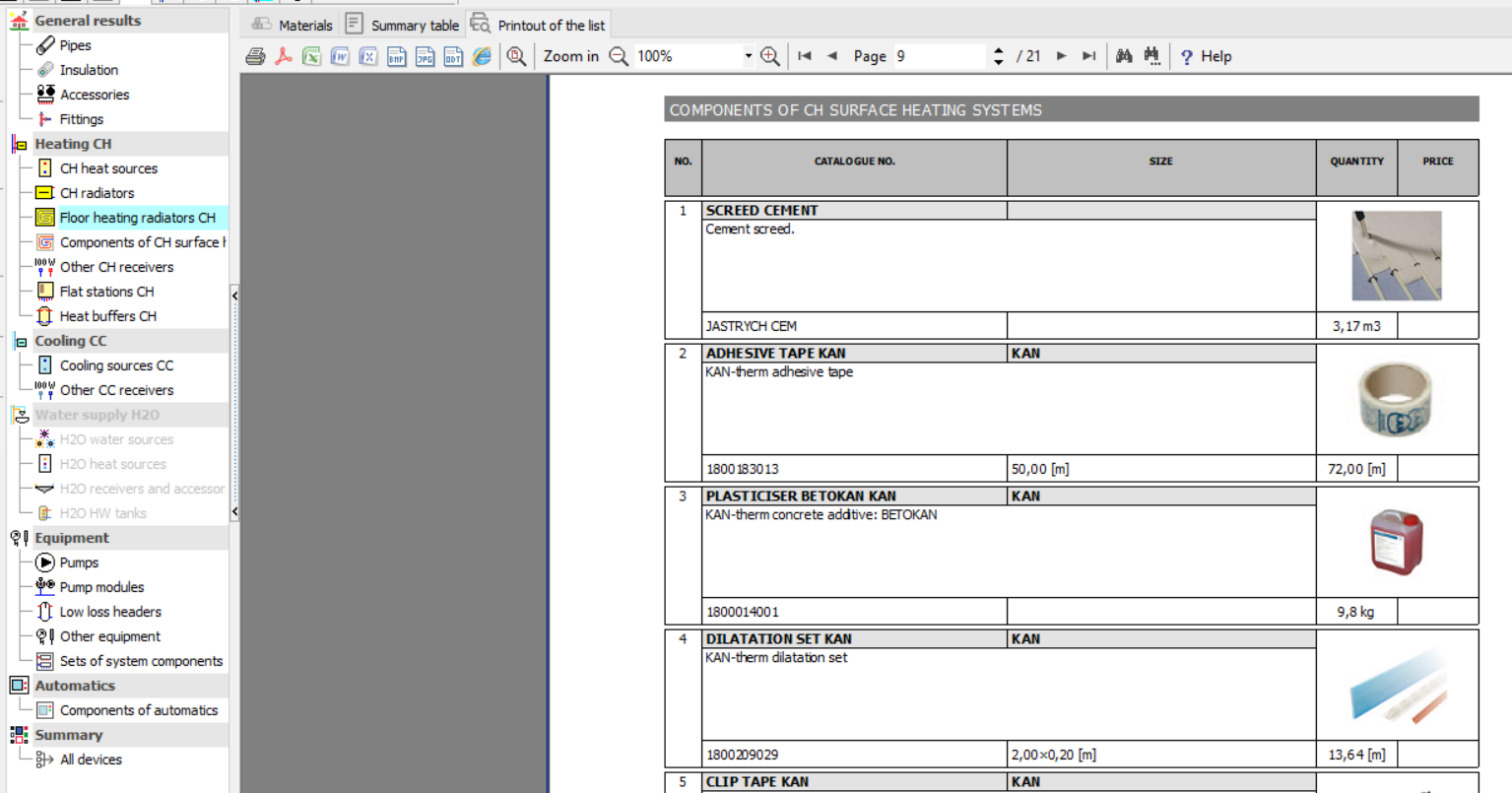
In addition, a summary with all devices present in the project is generated. In this summary, filters which allow you to display only the items relevant from the user's point of view can be declared.

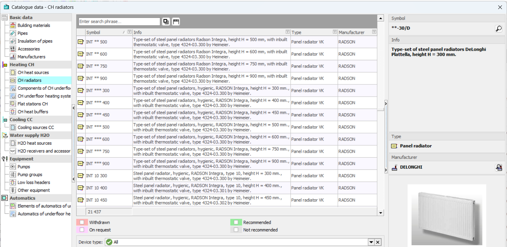
Changed module for viewing catalog data and selecting devices from catalogs
A modern layout has been introduced in the Catalog Data, allowing for more convenient browsing. The possibility to quickly search and filter data has been added
Improvements related to drawing pipes
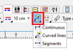
The mode of drawing pipes as curves has been introduced.
Note!!!
Curves are connected to the radiators (floor and convection) and manifolds only. They are not connected to other pipes and other devices.
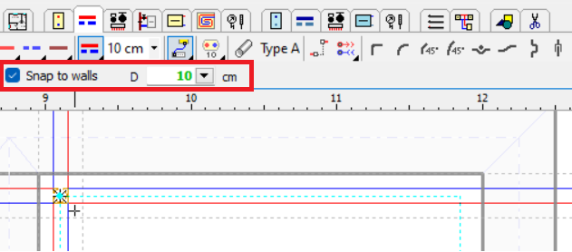
The Snap to walls option makes it easier to draw pipes at a preset distance from the walls.
The Show errors as exclamation points function button, located in the lower right corner of the Drawing with data window, will enable the display of exclamation points on unconnected pipe ends.
Improvements in graphics
A new module supporting DXF and DWG drawings has been introduced. Loading large drawings is now several times faster.
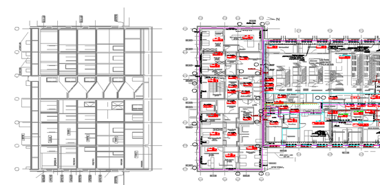
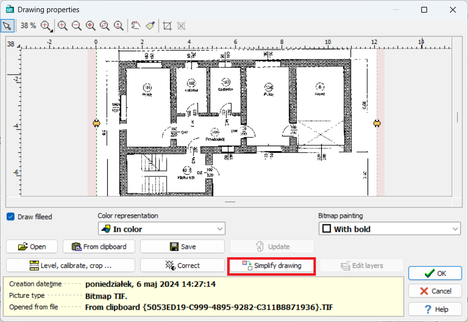
For very large drawings which cause the program to slow down, the Simplify drawing (Upraszczaj rysunek) function can be used. Note, however, that in many cases this will result in a loss of drawing quality.
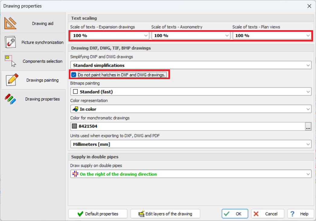
The ability to scale texts in drawings has been added in Drawing properties (Właściwości rysowania).
Text scale 80%
Text scale 110%
An option to disable hatch painting in DXF and DWG drawings is available. Disabling hatch painting speeds up the program for large drawings.